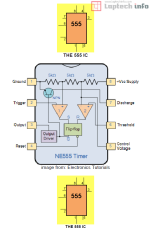
What is 555 IC?
The 555 is an 8-pin chip that can be turned into lots of different things (building blocks). The circuit inside the 555 is just an amplifier with 2 inputs and an output.The parts you add to the chip determine the final result (effect). In most cases you add a capacitor and resistor to produce a circuit known as a TIME
DELAY CIRCUIT and the chip has a detection-pin and an amplifier (also called a power amplifier) to produce an output.
It is not just a "timer," "delay" or "oscillator" but is capable of being converted into these and
maybe 100 other circuits. Just call it the "555"

The 555 HOW IT WORKS
To understand how the 555 works, you need to know how to connect pins 2 and 6.What you should know is as follows:
Pins 2 and 6 should never be left disconnected because doing so will cause the 555's output to occasionally be LOW or HIGHDue to their HIGH IMPEDANCE, pins 2 and 6 have the ability to detect static electricity and occasionally turn the 555 on or off.
Here are the 4 possibilities for pins 2 and 6:
The four options for pins 2 and 6 are as follows in the Table below:
| Pin 2 LOW | Pin 6 LOW | Pin 3 HIGH | Pin 2 controls the 555 IC. Pin 6 Has no effect |
| Pin 2 LOW | Pin 6 HIGH | Pin 3 HIGH | Pin 2 controls the 555. Pin 6 has NO effect. |
| Pin 2 HIGH | Pin 6 LOW | Pin 3 LOW | Pin 2 controls the 555.(the 555 does not turn on) |
| Pin 2 HIGH | Pin 6 High | Pin 3 LOW | Pin 2 controls the 555. (the 555 does not turn on) |
Connect pin 2 and 6 together. Take both HIGH . . . .. Pin 3 LOW (toggle Mode)
Connect pin 2 and 6 together. Take both LOW . . . .. Pin 3 HIGH (toggle Mode
Toggle Mode is also called INVERTER MODE . . . The output is opposite to the input. The 555 takes 10mA ALL THE TIME . . . even when the output is LOW
